1. ETCS Traffic Signal Control System
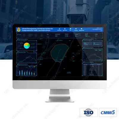
The ETCS® traffic signal control system communicates with the traffic light controllers in real time through various networking methods, realizing the perception of the traffic situation at the intersections and the control of outfield devices. The main control modes are self-adaptive optimal control, dynamic regional coordinated control, inductive control, overflow control, special duty control, bus traffic priority control, and unified control of multi-brand traffic light controllers. In addition, the system can exchange data with the Internet and integrated management and control platform to complete collaborative optimal control; At the same time, the system also supports vehicle-road collaboration and communicating with roadside IoT devices.
The ETCS® traffic light system focuses on improving the traffic capacity of roads and alleviating urban traffic congestion. While promoting big data applications and intelligent control, it also focuses on the ease of use of the system and improves user experience.
1.1 System Structure
The traffic light system supports C/S and B/S architecture and realizes traffic control based on Windows/Linux platform. The structure is shown below:

1.2 Physical Structure

1.3 System Function
Ageot® regional green signal efficiency optimization technology is based on virtual detection, logical operation, and full IoT. It integrates traffic signal timing artificial intelligence and delay minimization optimization model into the regional green signal efficiency optimization model, realizing "normalization" of different evaluation results. Applied in the actual control, the traffic light system can effectively reduce the traffic delay and improve the traffic service level.
1.4 System Feature
- The traffic light system can complete the wide-area inter-regional flow balance control and the self-adaptive and coordinated control of sub-intervals, sub-areas and intersections within the region;
-
Can automatically match a variety of control parameters to realize the hierarchical coordinated and optimal control of the back-end and intersections and the mixed control of multiple scenarios;
-
Can realize the adaptive control of multi-mode mixed intersection, multi-lane convergence, variable lane, tidal flow lane(reversible lane) and waiting area through virtual detection, logic operation, window control and other functions;
-
Can realize full IoT perception and intelligent operation and maintenance functions of outfield devices through HiPLC (High-speed Power Line Communications) technology and F5G all-optical technology.
-
Can be connected with multi-brand traffic light controllers to achieve unified platform control.
1.5 System Applicability
- The traffic light system can be applied to different groups, road conditions of urban traffic;
- Can be applied to intersections of complex traffic data or non-precise detection; Can well realize the real-time and stability of system control with the high stability and fault-tolerant control of the system;
- Standard version (conventional simple application) and professional version (professional technicians) client software suitable for different operators.
Standard Version--for simple daily application configuration

Professional Version--for professional technicians to finely control and manage intersections

2. Internet + Signal Control
2.1 Scenario
When there are insufficient or even no detection equipment at intersections or in the area, Internet data is used as the detection data or control strategy for trunk line or regional signal control to trigger the threshold value to achieve balanced and optimized control.

2.2 Solution
Determine the degree of road congestion in the area through analysis of Internet big data, especially the real-time traffic conditions on maps, and perform balanced control on intersections in the area. Can be combined with the entity detectors for control.
2.3 Scenario Configuration
Traffic Light Controller + Traffic Light + Traffic Signal Control and Management Platform Software + Urban Road Traffic Big Data Fusion Processing Module

3.Overflow Control
3.1 Scenario
As the distance between some intersections is shorter or there are fewer exit lanes, queues are prone to overflow to upstream intersections when signal timing is unreasonable or during rush hours. This not only wastes green time, but also causes vehicles from other directions at upstream intersections to be unable to pass during the green time, thus causing congestion at the intersection and leading to chain congestion at surrounding intersections.

3.2 Solution
(1) Install the detector 30-50 meters away from the exit in the direction prone to overflow.
(2) The detector uses logical operations to determine in real time whether the vehicle queue has reached the detection position.
(3) When it detects that the vehicle queue has reached the detection position, it stops releasing the green light into that direction and turns to release the other direction to prevent the vehicles from spilling back into the intersection.
3.3 Scenario Configuration
Traffic Light Controller + Traffic Light + Geomagnetic / Radar / Video Detection Equipment + Traffic Signal Control and Management Platform Software + Overflow Control Module

4.Special Duty Plan
4.1 Scenario
When required to perform a variety of special duties, fast and accurate control of traffic lights is needed.

4.2 Solution
(1) Preset the special duty routes and plans in the client software. Manual type and automatic type.
(2) Manual type: At the beginning of the plan, the special duty plan of each intersection is manually controlled according to the actual situation.
(3) Automatic type: Preset the activation interval of the special duty plan of each intersection. After the special duty plan of the first intersection is manually activated, the special duty plan of the subsequent intersections is automatically activated after the interval time.
4.3 Scenario Configuration
Traffic Light Controller + Traffic Light + Guard Task Control Panel + Traffic Signal Control and Management Platform Software + Special Duty Plan Control Module

5.Emergency Control Plan
5.1 Scenario
During some large-scale events or holidays, there will be a large gathering of people and vehicles, which may lead to some emergencies. It is necessary to respond to and handle the emergencies quickly, such as: traffic restriction, no passing, diversion.

5.2 Solution
Set up targeted emergency control plans for the intersections in the area and grade the plans for different scenarios. Run the emergency control plans in different levels according to the actual situation on site. Run the plan with one click in special circumstances.
5.3 Scenario Configuration
Traffic Light Controller + Traffic Light + Traffic Signal Control and Management Platform Software + Emergency Control Plan Control Module

6.Vehicle-Infrastructure Cooperative Application
6.1 Scenario
Vehicles interact with the signal controller for information. The signal controller pushes information such as the color status of the traffic light, countdown timer, and recommended speed of the green wave to the vehicle. The vehicle can transmit information such as its own position and speed to the signal controller, which carries out priority control or optimization of the timing scheme.

6.2 Solution
Install the OBU on the vehicle, the RSU on the roadside, and the vehicle-infrastructure cooperative router in the signal controller to realize information exchange between the signal controller, the RSU, and the OBU.
The signal controller can push real-time light color status, countdown timer and other intersection information and green wave recommended speeds, guidance information and other traffic information to vehicles.
Vehicles can push real-time location, speed and other information to signal controller, which can perform priority control and intersection scheme optimal control based on this information.
6.3 Scenario Configuration
Traffic Light Controller + Vehicle-Infrastructure Cooperation Router
7.Intelligent PLC-IoT
7.1 Scenario
The conventional method of inspecting intersection signal controller, lamps, countdown timers and other external devices not only consumes a lot of manpower and material resources, but also often results in failure to deal with faults in a timely manner.

7.2 Solution
Realize the IoT of signal controller and various peripherals through HiPLC technology. Regularly detect all kinds of devices, and alarm in real time when the device fails, so that the command center can quickly arrange the maintenance personnel to go to the scene in time to dispose of the faults. Save the manpower and material resources for inspection, and solve the pain point of the discovery and disposal of faults in a timely manner.
7.3 System Feature
- Break the traditional way; Realize power supply and communication with a pair of power lines;
- PLC-loT solves the problems of difficult wiring of traditional wired communication and unstable wireless communication; Use existing power lines to save construction and deployment costs, simplify engineering processes, and shorten construction arrangement period;
- Realize low-cost IoT of front-end traffic devices such as intersection traffic lights, countdown timers, pedestrian crossing buttons, which is in line with the future development direction of intelligent transportation;
- Equipment networking, real-time perception of the normal working conditions, automatic fault detection, intelligent operation and maintenance.
7.4 Scenario Configuration
GJK-10 Traffic Light Controller + Traffic Light and Other End Equipment + Traffic Signal Control and Management Platform Software + Embedded Signal Control Edge Gateway Control Module

8. F5G All-Optical Intelligent IoT
8.1 Scenario
The conventional networking method used to connect traffic signal controllers, traffic lights and other external equipment has a long construction period, low reliability, difficult operation and maintenance, and often leads to untimely handling of faults.

8.2 Solution
Through all-optical and low-voltage technology, distributed deployment, and one photoelectric composite cable, power supply and communication are realized; simple deployment, safe and reliable. It can detect external devices and alarm in real time when the device fails, realizing precise and intelligent operation and maintenance.
(1) Break the traditional way; Realize power supply and communication with one photoelectric composite cable;
(2) Low-voltage, ring network, distributed deployment, safer and more reliable;
(3) Solve the problems of difficult wiring of traditional wired communication and unstable wireless communication; Use existing power lines to save construction and deployment costs, simplify engineering processes, and shorten construction arrangement period;
(4) Equipment networking, real-time perception of the normal working conditions, automatic fault detection, intelligent operation and maintenance.
8.3 Scenario Configuration
GJK-F1 Traffic Light Controller + Distributed Light Driver + All-optical ONU + All-optical OLT + Traffic Signal Control and Management Platform Software
9.Regional Control
9.1 Scenario
When the congestion in the region is severe and cannot be alleviated by a single intersection or a trunk line, regional control is used to realize balanced optimal control.

9.2 Solution
Set up detection at key nodes and main traffic entry and exit points in the area. Formulate different control strategies for different detection conditions. When it is detected that the traffic in the area meets the set conditions, the intersections in the area will run the control scheme under the corresponding control strategy.
9.3 Scenario Configuration
Traffic Light Controller + Traffic Light + Geomagnetic/Radar/Video Detection Equipment + Traffic Signal Control and Management Platform Software + Regional Control Module

10.Self-Adaptive Control
10.1 Scenario
When the intersection is relatively isolated, with less correlation with upstream and downstream intersections, the characteristic curve of vehicle data is relatively fixed, and the fixed timing can not fully meet the traffic demand, self-adaptive control can be used to realize the automatic change of traffic light timing.

10.2 Solution
Install the detector at the stop line of the intersection to detect the vehicle saturation of the green time. The green time in each direction is increased or decreased according to the vehicle saturation in each direction.
10.3 Scenario Configuration
Traffic Light Controller + Traffic Light + Geomagnetic/Radar/Video Detection Equipment + Traffic Signal Control and Management Platform Software + Traffic Signal Self-Adaptive Control Module

11. Inductive Control
11.1 Scenario
When the intersection is relatively isolated, with less correlation with upstream and downstream intersections, the characteristic curve of vehicle data is relatively fixed, and the fixed timing can not fully adapt to the rapidly changing demands, inductive control can be used to realize the automatic change of traffic light timing.

11.2 Solution
Install the detector at the intersection 15-30 meters away from the stop line, increase the green time when a vehicle passes within the minimum time, and change the light to red when no vehicle passes.
11.3 Scenario Configuration
Traffic Light Controller + Traffic Light + Geomagnetic/Radar/Video Detection Equipment + Traffic Signal Control and Management Platform Software(Monitoring)

12.Coordinated Control
12.1 Scenario
When multiple intersections on the trunk line are in close proximity, coordinated control of intersections can reduce the number of times vehicles stop on the road and improve driving comfort.

12.2 Solution
(1) Coordinated control is divided into static coordinated control and dynamic coordinated control.
(2) Static coordinated control: Based on experience or historical traffic flow data, coordinate the coordination line in multiple time periods. Ensure that the intersection cycle in the line is consistent, and achieve "green light all the way" by adjusting the phase difference.
(3) Dynamic coordinated control: By detecting the number of vehicles at each intersection on the trunk line, dynamically adjusting the common cycle of the main line and coordinating the phase difference to realize "green light all the way".
12.3 Scenario Configuration
Traffic Light Controller + Traffic Light + Geomagnetic/Radar/Video Detection Equipment + Traffic Signal Control and Management Platform Software + Traffic Signal Self-Adaptive coordinated Control Module

13.Intelligent Multi-Lane Convergence
13.1 Scenario
Multiple roads converge into one road, the number of entrance lanes is greater than the number of exit lanes, the exit is easily saturated and interweaving is prone to occur; Traffic violations such as vehicles competing for lanes, changing lanes to squeeze in, and changing lanes illegally further aggravate congestion and are very likely to cause traffic accidents.

13.2 Solution
(1) Install traffic lights and lane information signs on the entrance road.
(2) For the weaving area with chaotic traffic order, use traffic lights to control the traffic flow outside the weaving area and standardize the traffic order in the weaving area.
(3) Determine the release method of each upstream entrance according to the "capacity" size (number of lanes) of the downstream exit.
(4) Reasonably allocate the release volume (green time) of each upstream entrance to achieve the purpose of balanced traffic flow.
(5) Install detection equipment at the exit to detect the congestion of the exit. When the exit is slow or congested, adjust the release plan to reduce the release time of each lane.
(6) When queue detection equipment is installed, control the green signal ratio of each lane according to the queue situation of each lane to achieve the control purpose required by users.
13.3 Scenario Configuration
Traffic Light Controller + Traffic Light + Geomagnetic/Radar/Video Detection Equipment + Traffic Signal Control and Management Platform Software + Intelligent Multi-Lane Convergence Control Module

14.Variable Lane
14.1 Scenario
The traffic flow of straight and left-turn vehicles is unbalanced during the morning and evening rush hours. Set a lane as a variable lane and change the lane attributes according to the straight and left-turn traffic conditions.

14.2 Solution
(1) Install a variable lane display screen 30-80 meters away from the stop line to indicate the current lane attributes.
(2) Install a dedicated variable lane traffic light at the intersection to indicate straight or left turn according to the current lane attributes.
(3) When there is no detector, configure the scheme in different time periods based on experience.
(4) When there is a detector, use intelligent variable lane control. Perform queue detection on the straight and left turn lanes, and determine the variable lane attributes based on the queue situation.
14.3 Scenario Configuration
Traffic Light Controller + Traffic Light + Geomagnetic/Radar/Video Detection Equipment + Variable Lane Display Screen + Traffic Signal Control and Management Platform Software + Variable Lane Control Module

15.Tidal Flow Lane
15.1 Scenario
The traffic flow in both directions of a road varies greatly over a period of time. One direction is congested, while the other direction has fewer vehicles, resulting in a low lane utilization rate. Set the lane in the direction with fewer vehicles as the tidal flow lane(reversible lane), which changes the lane direction according to the traffic conditions.

15.2 Solution
(1) Install double-sided lane control traffic lights, traffic signs and information prompt screens at the starting and ending points of the tidal flow lane(reversible lane), and draw corresponding lane markings.
(2) Tidal flow lane(reversible lane) control is linked with upstream and downstream intersections. Reserve sufficient clearing time when the tidal lane is switched. During the clearing time, vehicles in both directions are prohibited from entering the tidal flow lane, and only vehicles already in the tidal flow lane are allowed to exit. The length of the clearing time is related to the length of the tidal flow lane and the green signal ratio of the upstream and downstream intersections in that direction.
15.3 Scenario Configuration
Traffic Light Controller + Tidal Flow Lane Traffic Light + Geomagnetic/Radar/Video Detection Equipment + Traffic Signal Control and Management Platform Software + Tidal Flow Lane Module

16.Bus Traffic Priority
16.1 Scenario
Buses or special vehicles need to have priority at intersections. Allow buses or special vehicles to pass through intersections without stopping or with minimal stopping.

16.2 Solution
(1) Mark the dedicated bus lanes; Install bus traffic priority signs and traffic lights.
(2) Install a set of RFID/other detection equipment 100-200 meters away from the stop line to detect that the vehicle has entered the detection zone; Install a set of RFID/other detection equipment 20-30 meters away from the stop line to detect that the vehicle has approached the intersection.
(3) When the bus arrives at the far detection point, calculate the time it takes for the vehicle to arrive at the intersection; Use methods such as extending the green time, shortening the red time, and inserting phases to realize bus traffic priority. The near detection point is used to detect whether the vehicle has arrived at the intersection and fine-tune the control plan.
16.3 Scenario Configuration
Traffic Light Controller + Traffic Light + RFID/Geomagnetic/Radar/Video Detection Equipment + Traffic Signal Control and Management Platform Software + Urban Bus Traffic Priority Control Module

Hot Tags: traffic light system, China traffic light system manufacturers, suppliers, factory